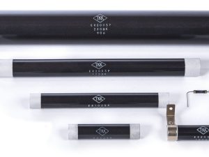
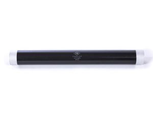
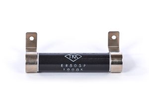
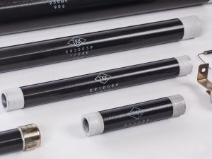
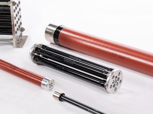
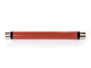
APPLICATIONS
- Power supply circuits
- Dummy loads
- Circuits for protecting against parasitic oscillation
- PT protection
- High-frequency circuits
- Accelerators
- Other high-current circuits
- Ultrasonic devices
- Other applications: far-infrared heaters, microwave absorbers
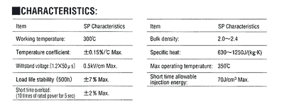
CHARACTERISTICS
| Items | Characteristic Value |
| Normal operating temperature | 300℃ |
| Maximum Operating Temperature | 350℃ |
| Temperature Coefficient | ±0.15%/℃ |
| Withstand Voltage (1.2 / 50µs) | 0.5kV/cm |
| Rate of change of resistance when current is applied (rated time of 500 h) |
±10% |
| Short-time overloading (10 times × 5 sec) | ±2%(MAX) |
| Short-time injection capacity | 70J/cm3 |
| Bulk specific gravity | 2.0- 2.4 |
| Specific Heat | 630J/(kg⋅K) |
| Thermal expansion coefficient | 3- 5×10⁻⁶(/℃) |
SP STANDARD SPECIFICATIONS:
| Model | Rated Power (W) |
Dimension(mm) | Cross Sections (cm2) |
Effective length(cm) |
Volume (cm3) |
Resistance Value Range (Ω) |
Maximum Operating Impulse Voltage (kV) *1 1.2/50µs |
Allowable Energy Injected (J) |
Unit Weight (g) |
|||
| φD | φd | L | L1 | |||||||||
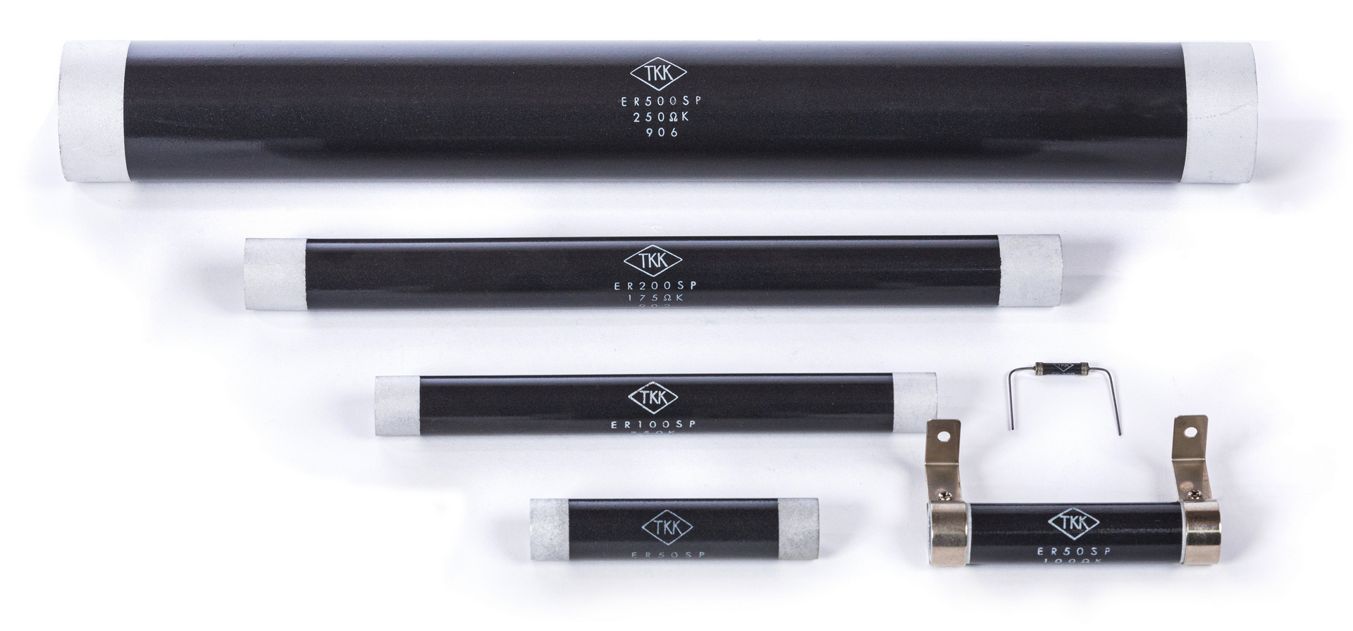
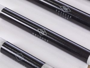
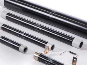
| ER3SP | 3 | 4.5±1.0 | – | 20±1 | 38±2 | 0.13 | 1.4 | 0.18 | 1.0- 390 | 0.5 | 11 | 0.5 |
| ER5SP | 5 | 8.5±1.0 | – | 25±1 | 38±2 | 0.50 | 1.8 | 0.90 | 1.0- 150 | 0.5 | 63 | 3 |
| ER10SP | 10 | 8.5±1.0 | – | 40±1 | 38±2 | 0.50 | 3.3 | 2.01 | 1.0- 270 | 1 | 110 | 4 |
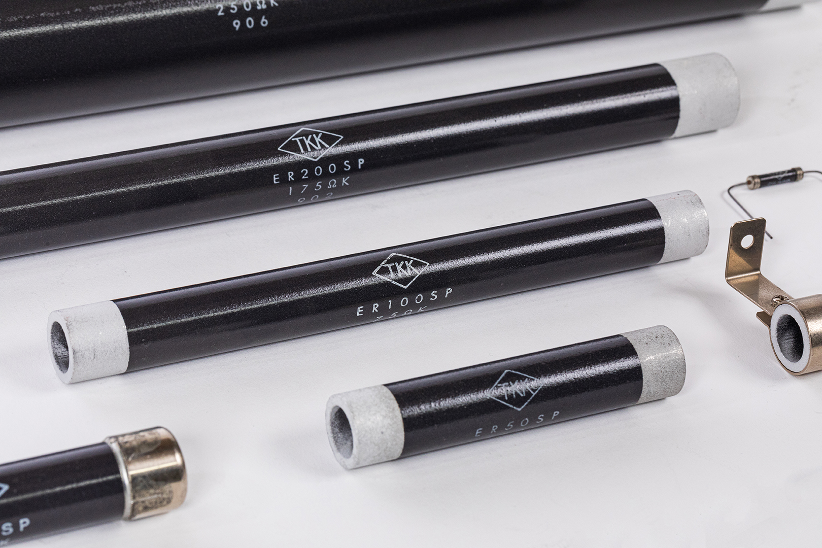
| ER20SP | 20 | 14±0.5 | 8 | 60±1 | 10±2 | 1.04 | 4 | 6.22 | 0.33- 220 | 2 | 290 | 14 |
| ER30SP | 30 | 14±0.5 | 8 | 80±1 | 10±2 | 1.04 | 6 | 7.67 | 0.47- 230 | 3 | 430 | 19 |
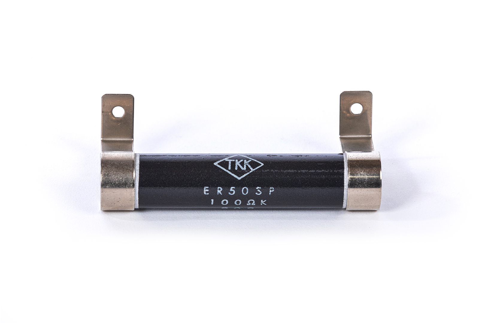
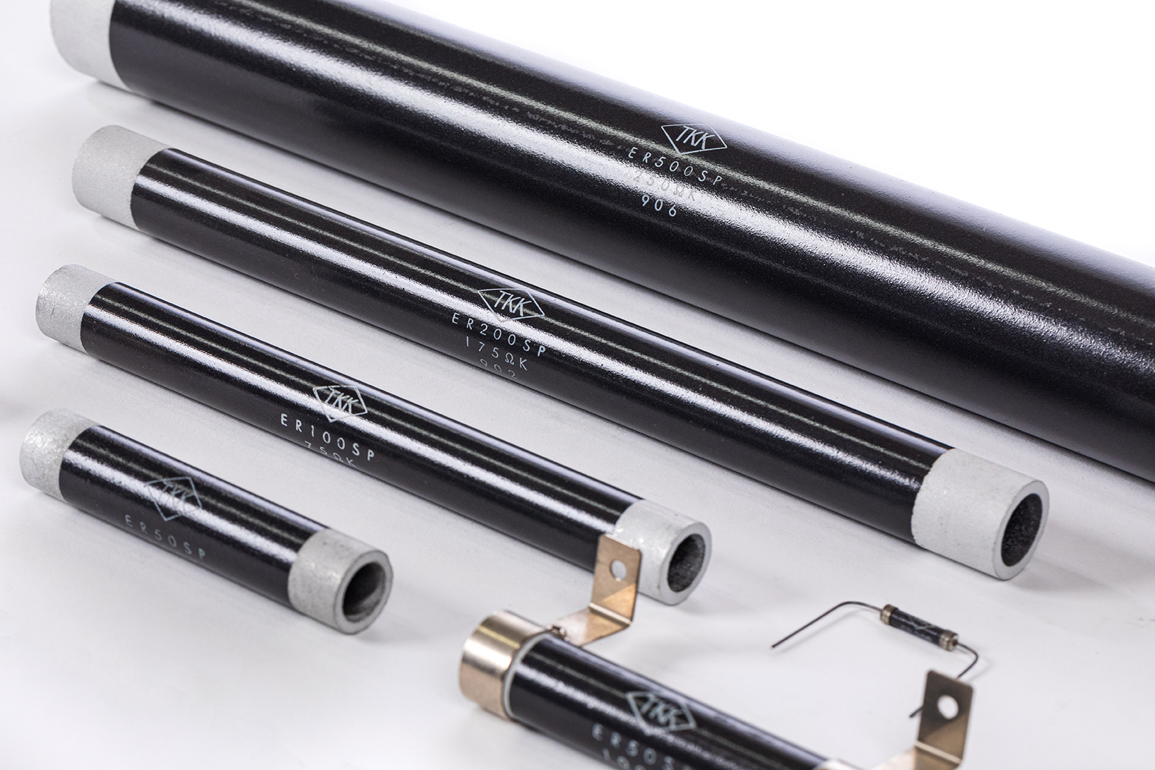
| ER50SP | 50 | 20±0.8 | 14 | 100±1 | 13±2 | 1.60 | 7.4 | 11.9 | 0.47- 270 | 4 | 830 | 36 |
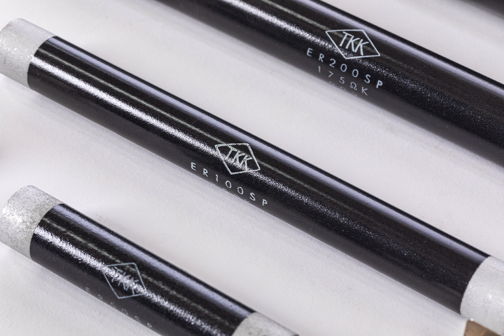
| ER100SP | 100 | 20±0.8 | 14 | 200±2 | 15±2 | 1.60 | 17 | 27.2 | 1.0- 680 | 8.5 | 1900 | 72 |
| ER150SP | 150 | 25±1.0 | 18 | 250±2 | 22±2 | 2.36 | 20.6 | 48.7 | 0.82- 520 | 10 | 3400 | 133 |
| ER200SP | 200 | 25±1.0 | 18 | 300±2 | 22±2 | 2.36 | 20.6 | 60.5 | 1.0- 680 | 12.5 | 4240 | 160 |
| ER300SP | 300 | 40±1.3 | 32 | 300±2 | 22±2 | 4.52 | 25.6 | 116 | 0.56- 330 | 12.5 | 8100 | 305 |
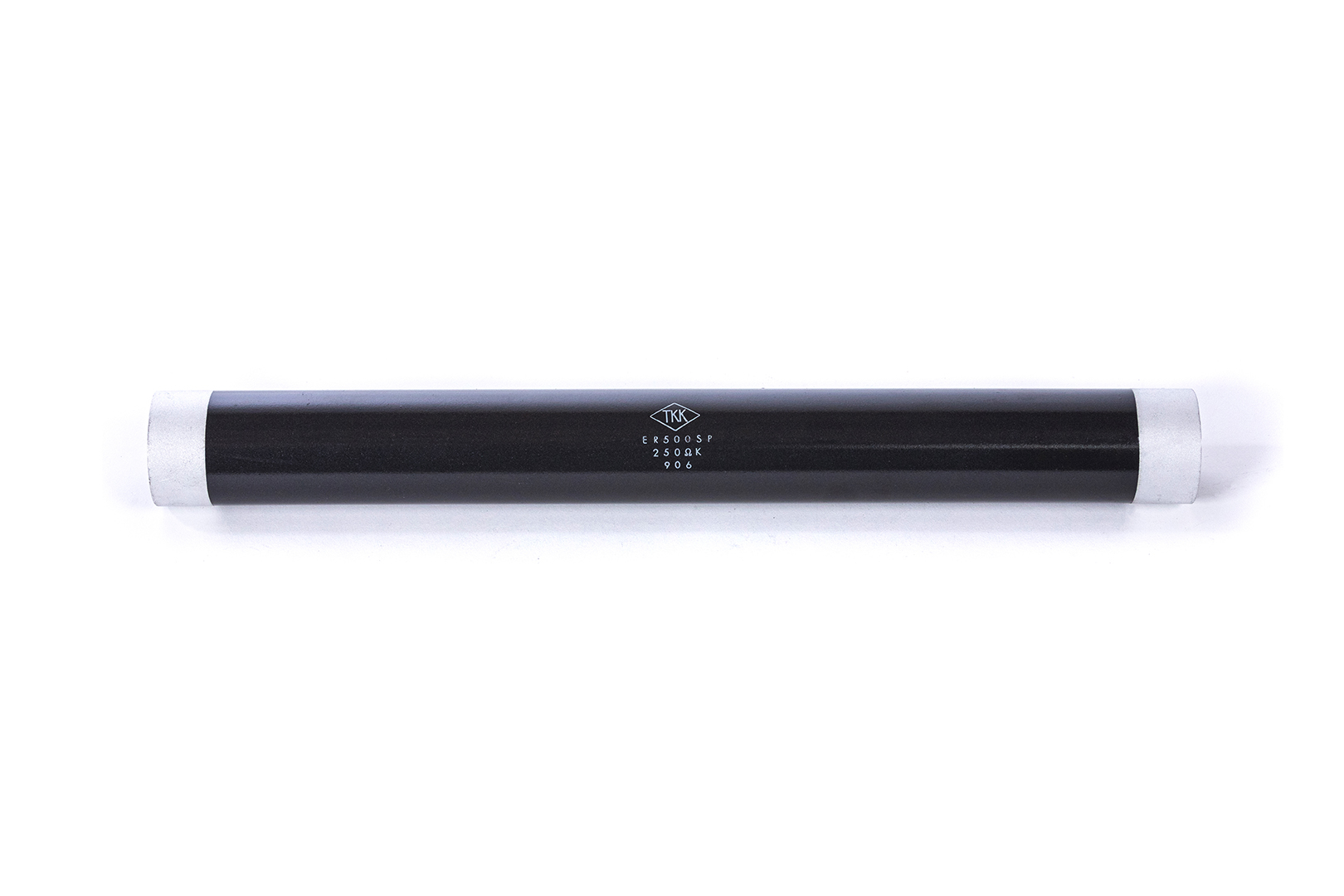
| ER500SP | 500 | 50±1.5 | 40 | 450±2 | 25±2 | 7.07 | 40 | 283 | 0.56- 330 | 20 | 19800 | 716 |

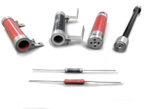
ER3SP through ER10SP will be supplied with lead wires.
ER20SP through ER500SP will be supplied with terminals as option, if so requested with an order. (The details on the terminals are shown at page 12).
SPT STANDARD SPECIFICATIONS (Vertical Mounting Type):
| Model | Rated Power (W) |
Dimensions (mm) | Maximum Operating Impulse Voltage (kV) *1 1.2/50µs |
|||||||
| φB | L | L1 | D | φC | φS | M | E | |||
| ER20SPT | 20 | 14 | 60 | 9 | 70 | 16 | 3.2 | 31 | 10 | 2 |
| ER30SPT | 30 | 14 | 80 | 9 | 90 | 16 | 3.2 | 31 | 10 | 3 |
| ER50SPT | 50 | 20 | 100 | 12 | 110 | 22 | 4.2 | 42 | 10 | 4 |
SPY STANDARD SPECIFICATIONS (Horizontal Mounting Type):
| Model | Rated Power (W) |
Dimensions (mm) | Maximum Operating Impulse Voltage (kV) *1 1.2/50µs |
||||||||||
| φB | L | L1 | φS | C | E | D | F | F0 | M | t | |||
| ER20SPY | 20 | 14 | 60 | 9 | 3.2 | 70 | 103 | 90 | 16 | 4.2 | 16 | 0.8 | 2 |
| ER30SPY | 30 | 14 | 80 | 9 | 3.2 | 90 | 123 | 110 | 16 | 4.2 | 16 | 0.8 | 3 |
| ER50SPY | 50 | 20 | 100 | 12 | 4.2 | 110 | 143 | 130 | 16 | 4.2 | 16 | 0.8 | 46 |
| ER100SPY | 100 | 20 | 200 | 12 | 4.2 | 210 | 243 | 230 | 16 | 4.2 | 16 | 0.8 | 6 |
| ER150SPY | 150 | 25 | 250 | 21 | 5.2 | 262 | 315 | 300 | 26 | 6 | 26 | 1.0 | 6 |
| ER200SPY | 200 | 25 | 300 | 21 | 5.2 | 312 | 365 | 350 | 26 | 6 | 26 | 1.0 | 6 |
| ER300SPY | 300 | 40 | 300 | 21 | 5.2 | 320 | 380 | 360 | 40 | 10 | 40 | 1.5 | 6 |

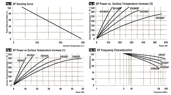
Notes on Using the SP Resistors
- The SP resistors are susceptible to surge voltage. We recommend using them at about 50% (0.25 kV/cm) of the maximum operating impulse voltage.
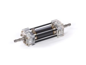
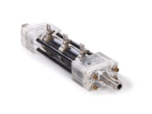
- The SP resistors can be used in oil or water as are. For water-cooled applications, we will attach a brass electrode.
Use pure water with a resistivity of 1 MΩ•cm or higher (an electrical conductivity of 1 µS/cm or lower) as the cooling water. - The dielectric strength decreases at a high surface temperature greater than or equal to 300℃.
- Install SPY or SPT resistors in a vibration-free location.
- The SPY and SPT resistors include insulators. Overtightening the screws can cause breakage. We recommend that the tightening torque be 0.3 N•m for M3 screws, and 0.4 N•m for M4 screws.
