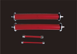
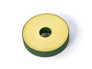
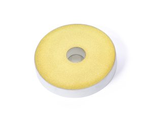
APPLICATIONS
- Impulse voltage generators
- Charging/discharging of capacitors
- X-ray generators
- Protection of electrostatic precipitators
- Protection of rectifiers
- Dummy loads
- High-frequency circuits
- Surge absorption
- Disconnectors and grounding resistors
- Fusion devices
- Accelerators
- Distributors
- Other high-voltage circuits
Characteristics (Representative Value)
| Items | Characteristic Value |
| Maximum Operating Temperature | 250℃ |
| Temperature Coefficient | -0.15- -0.01%/℃ |
| Withstand Voltage (1.2 / 50µs) | See Figure |
| Rate of change of resistance when current is applied (rated time of 500 h) |
+ 15% or less |
| Short-time overloading (10 times x 5 sec) |
±2%(MAX) |
| Short-time injection capacity | 90J/cm3 |
| Bulk specific gravity | 2.20- 2.65 |
| Specific Heat | 630J/(kg・K) |
| Coefficient of Thermal Expansion | 5- 7×10⁻⁶(/℃) |
AS and ASH Standard Specifications
| Model | Rated Power (W) |
Dimensions(mm) | Cross Sections (cm2) |
Effective Length (cm) |
Volume (cm3) |
Resistance Value Range (Ω) |
Maximum Operating Impulse Voltage (kV) *1 1.2/50µs |
Allowable Energy Injected (J) |
Single Weight(g) |
|||
| φD | φd | L | L1 | |||||||||
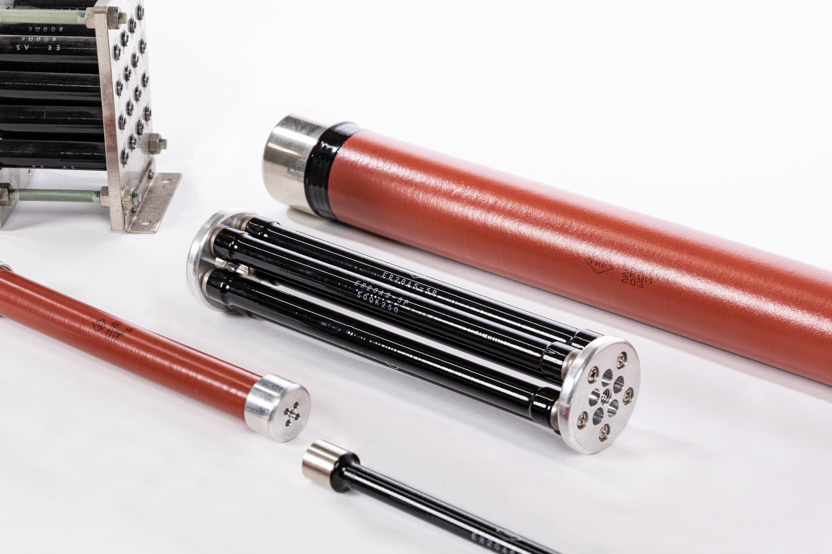
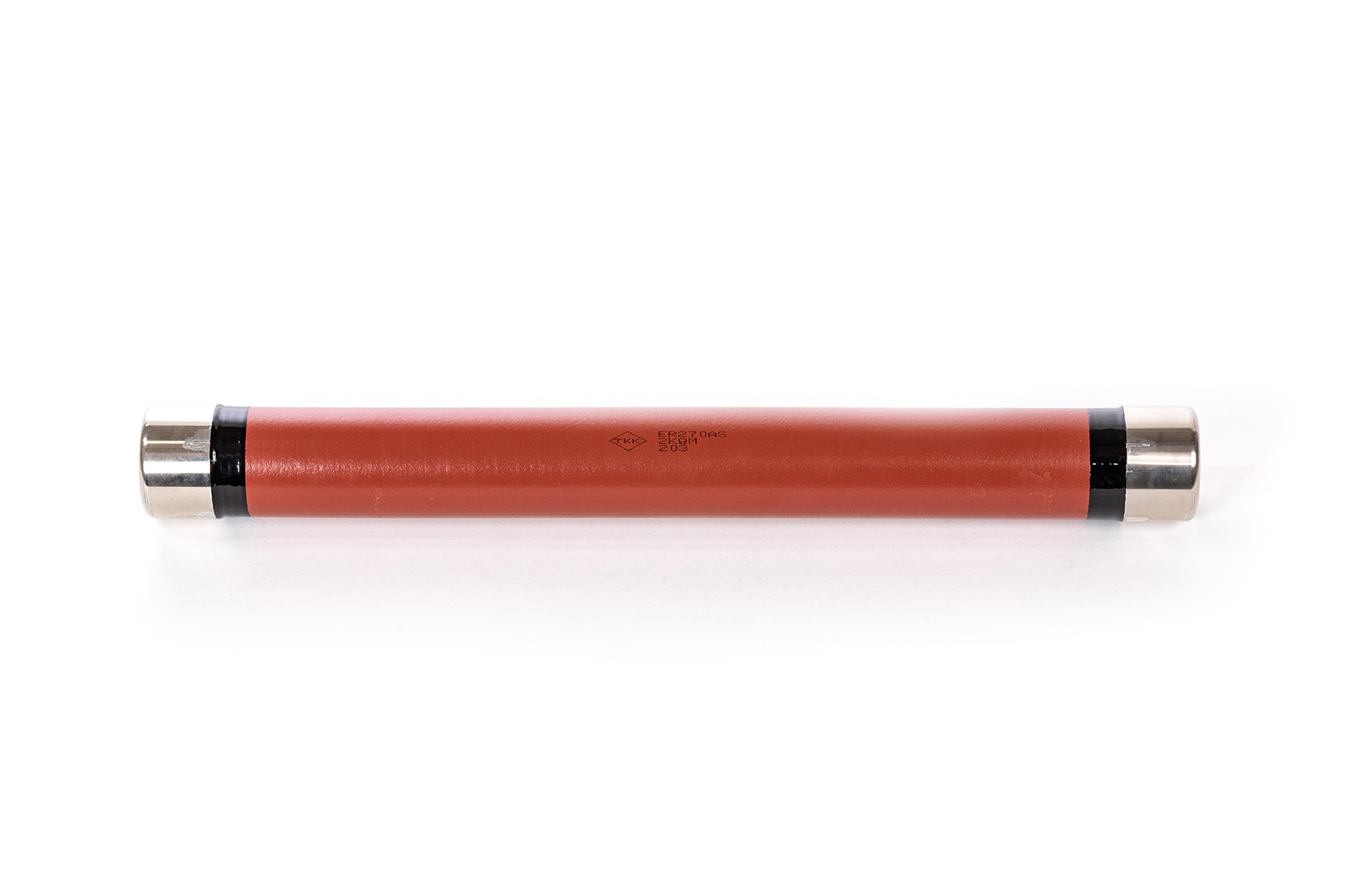
| ER2AS | 2 | 4.5±1.0 | – | 20±1 | 38±2 | 0.13 | 1.4 | 0.18 | 10- 56000 | 3.5 | 14 | 0.6 |
| ER3AS | 3 | 8.5±1.0 | – | 25±1 | 38±2 | 0.50 | 1.8 | 0.90 | 10- 18000 | 4.5 | 80 | 3 |
| ER5AS | 5 | 8.5±1.0 | – | 40±1 | 38±2 | 0.50 | 3.3 | 1.66 | 10- 33000 | 9 | 140 | 5 |
| ER10AS | 10 | 14±0.5 | 8 | 60±1 | 10±2 | 1.04 | 3.4 | 3.52 | 18- 22000 | 20 | 370 | 16 |
| ER20AS | 20 | 14±0.5 | 8 | 80±1 | 10±2 | 1.04 | 5.4 | 5.60 | 27- 27000 | 30 | 560 | 22 |
| ER30AS | 30 | 20±0.8 | 14 | 100±1 | 13±2 | 1.60 | 6.8 | 10.9 | 22- 22000 | 35 | 1060 | 42 |
| ER50AS | 50 | 20±0.8 | 14 | 200±2 | 15±2 | 1.60 | 16.4 | 26.3 | 47- 56000 | 70 | 2450 | 85 |
| ER80AS | 80 | 25±1.0 | 18 | 250±2 | 22±2 | 2.36 | 20 | 47.3 | 47- 47000 | 80 | 4360 | 157 |
| ER100AS | 100 | 25±1.0 | 18 | 300±2 | 22±2 | 2.36 | 25 | 59.1 | 56- 100000 | 100 | 5430 | 188 |
| ER150AS | 150 | 40±1.3 | 28 | 300±2 | 22±2 | 6.41 | 25 | 160 | 27- 27000 | 100 | 14760 | 510 |
| ER270AS | 270 | 50±1.5 | 38 | 450±2 | 25±3 | 8.29 | 39.4 | 327 | 22- 22000 | 160 | 29850 | 989 |
| ER20ASH | 20 | 12±0.2 | 10±0.5 | 200±2 | 19±0.1 | 0.79 | 15.35 | 12.1 | 10- 100000 | 85 | 1300 | 39 |
| ER40ASH | 40 | 12±0.2 | 10±0.5 | 300±2 | 19±0.1 | 0.79 | 23.35 | 19.9 | 20- 170000 | 100 | 2000 | 60 |
| ER60ASH | 60 | 16±0.2 | 14±0.5 | 400±2 | 19±0.1 | 1.54 | 35.35 | 54.4 | 10- 120000 | 150 | 5500 | 158 |
| ER80ASH | 80 | 16±0.2 | 14±0.5 | 500±3 | 19±0.1 | 1.54 | 45.35 | 69.8 | 15- 150000 | 185 | 7000 | 199 |
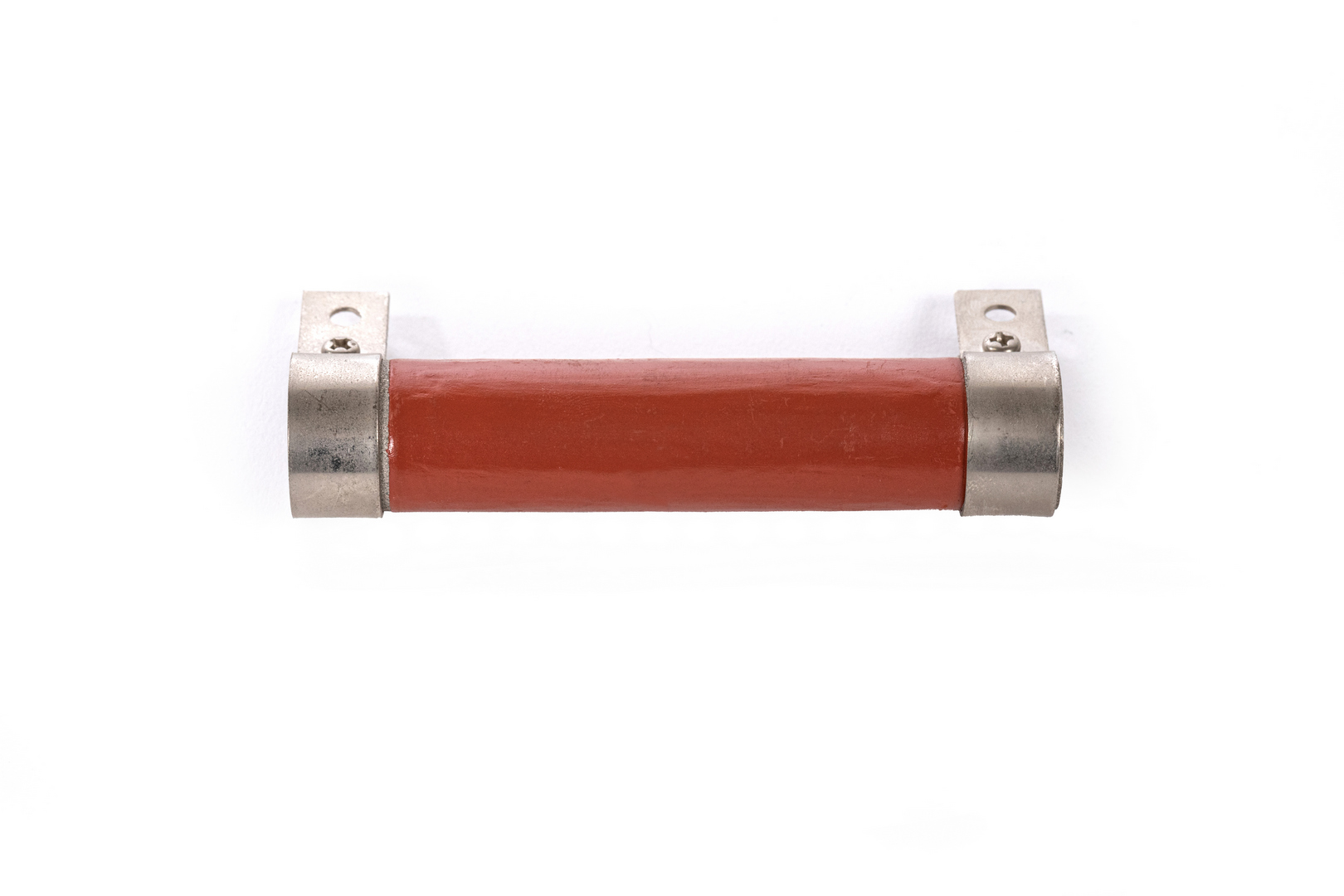
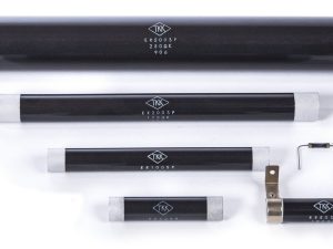
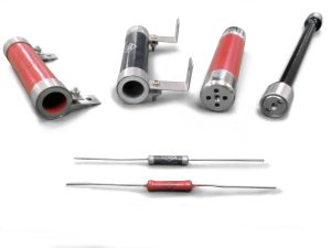
- The ER2AS to ER5AS models come with lead wires.
- Upon request, we will attach a standard terminal to any of the ER10AS to ER270AS models
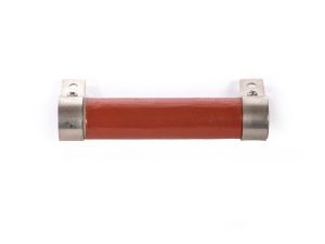
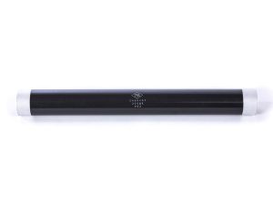
- All the ASH models are solid and come with terminal fittings.
- ※1 The maximum operating impulse voltage varies depending on the resistance value.
- Note: If using your resistor in oil, be sure to ask us to apply an oil-resistant coating (with a maximum operating temperature of 85℃) to the resistor.

Characteristic Data
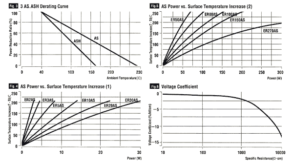
Notes on Using the AS and ASH Resistors
- The AS and ASH resistors have hygroscopic characteristics, which result in increased resistance. To minimize the increase in resistance, store resistors at room temperature in an environment with no moisture absorption.
- The resistance tends to increase gradually as voltage is applied. To use resistors for long periods of time, you need to set load conditions that ensure the surface temperature of the resistor does not exceed 100℃.
- Under high-voltage conditions, the resistance will decrease at a specific resistance of 2000 Ω•cm or higher. Check the operating conditions before use.
- The voltage coefficients of the AS and ASH resistors tend to vary significantly depending on the specific resistance and applied voltage. Check the operating conditions when using resistors for voltage division, measurement, or other applications where the resistance value matters when voltage is applied.
- Under high impulse voltage conditions, the electrode on resistors can spark at 100 Ω or less. Contact us for information about our resistors with anti-discharge protection or a modified electrode structure.
- Be aware that using a resistor with an inner diameter in oil will cause its resistance to increase by about 5% to 20% from the initial amount due to the level of sealing between the resistor and the electrode and other factors. For applications in oil, we recommend using an ASH.
